ST STM32H745 Dual Core AMP Demo
Core to core communication using Message Buffers
[RTOS Ports]
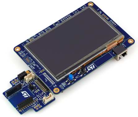
STM32H745I Discovery Board
This page documents a simple Asymmetric Multi Processing (AMP) core to
core communication demo implemented using
FreeRTOS message buffers.
It is accompanies by a separate article
that describes some of the internal implementation details.
The demo is preconfigured to run on the STM32H745I
Discovery Board and build with the IAR compiler and
Embedded Workbench IDE.
The STM32H7xx has one ARM Cortex-M4 core and one ARM Cortex-M7 core. Both cores run
the same ARMv7-M FreeRTOS port.
Embedded Workbench enables a productive feature rich development environment; it
ships with a fully thread aware FreeRTOS kernel plug-in and
enables both MCU cores to be debugged simultaneous.
IMPORTANT! Notes on using the FreeRTOS ARMv7-M (Cortex-M4 and M7) port
Please read all the following points before using this RTOS port.
- Source code organisation
- The demo application functionality
- Building and running the RTOS demo application
- Debugging the demo application - STLink
- Debugging the demo application - I-jet
- RTOS configuration and usage details
Also see the FAQ
My application does not run, what could be wrong?.
Source Code Organization
The FreeRTOS zip file download contains the source code for all the FreeRTOS ports, and
every demo application. That means it contains many more files than are required
to use the FreeRTOS STM32H745I dual core AMP demo.
See the
Source Code Organization page for information on the
zip file's directory structure. The IAR Embedded Workbench workspace for this demo
is located in the
FreeRTOS/Demo/CORTEX_M7_M4_AMP_STM32H745I_Discovery_IAR
directory. The project in the workspace contains two configurations, one for the Cortex-M4 core and one for the Cortex-M7 core.
The STM32H745 Dual Core Demo Application
Functionality
Message buffers are used to pass an ASCII representation of an incrementing number (so "0",
followed by "1", followed by "2", etc.) from a single 'sending' RTOS task (or 'thread') that
runs on the Arm Cortex-M7 core to two "receiving" RTOS tasks
running on the Arm Cortex-M4 core. The string changes length as the number of digits increases. There are two data message
buffers, one for each receiving task. To distinguish between the receiving
tasks one is assigned the task number 0, and the other task number 1.
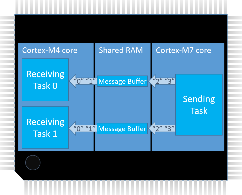 Hardware topology. Click to enlarge.
The Cortex-M7 task sits in a loop sending the ascii strings to each Cortex-M4 task. If a
receiving task receives the next expected value in the sequence it prints its
task number to the UART. If a receiving task receives anything else, or its
attempt to receive data times out, then it hits an assert() that prints an
error message to the UART before stopping all further processing on the Cortex-M4
core. The following pseudocode snippets demonstrate the structure of the sending
and receiving tasks respectively.
SendingTask()
{
for ever
{
Generate the next string in the sequence
Send the generated string to the first message buffer
Send the generated string to the second message buffer
}
}
Simplified psuedocode showing the structure of the sending task
|
ReceivingTask()
{
for ever
{
Read next message from the message buffer
configASSERT( Received message is next expected in sequence );
Write task number (0 or 1) to the UART
}
}
Simplified psuedocode showing the structure of the receiving tasks
|
When executing correctly a stream of "0"s will be written to the UART by the
receiving task assigned task number 0, with one 0 written each time that receiving
task receives the next expected message in the sequence. Likewise a stream of "1"s
will be written to the UART by the receiving task assigned task number 1. The demo
runs as fast as it can, the time taken to output characters to the UART being
the limiting factor. The control message buffer (see the Implementation section
below) becomes full because the sending task runs on the Cortex-M7 core, which is
clocked at twice the speed of the Cortex-M4 core, plus the sending task is not
throttled by the speed of the UART.
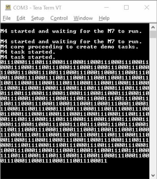 UART output when executing the demo
Implementation Details
The
separate article
that accompanies this demo provides a detailed explanation.
Important note:
The project will not build if the directory structure is different to
the directory structure used in official FreeRTOS zip file releases.
To build and run the demo application:
-
Ensure the parts database included with your IAR Embedded Studio for ARM
instillation includes the STM32H745. At the time of writing it was necessary
to manually download the
STM32Cube Package for STM32H7
to obtain a patch that updates the IAR installation. This will no longer
be necessary if you are using the latest IAR tools.
-
The demo outputs UART data via USB connector CN14 (marked STLink) on the STM32H745I Discovery Board.
Connect a USB cable between port CN14 on the STM32H745I Discovery Board and the
host computer (the computer that will be used to view the UART output)
and power the board up in order for the USB (virtual) COM port to enumerate
on the host. There are several power options, set by the
JP8 bank of jumpers.
-
Using a dumb serial terminal such as Teraterm on the host computer,
connect to whichever COM port was enumerated when the Discover Board was
connected and set the port settings to 115200 baud, with no parity
bits, 8 data bits, and 1 stop bit. An easy way to find the COM port
number is to see which port numbers are provided as options in the dumb terminal both with
and without the STM32H745I Discovery Board powered up.
-
Open FreeRTOS/Demo/CORTEX_M7_M4_AMP_STM32H745I_Discovery_IAR/Project.eww
from within the IAR Embedded Workspace IDE (or simply double click the file
to open it in Embedded Workbench).
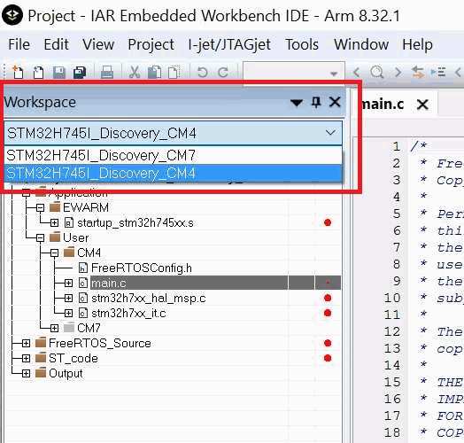
-
Use the drop down at the top of the Workspace window to select the
configuration for the Cortex-M4 core.
-
Select "Make" from the "Project" menu to build the project (or just press
F7).
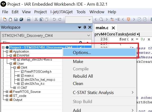
-
Open the project options dialog by right clicking the project in the Workspace
window and selecting "Options" from the pop up menu.
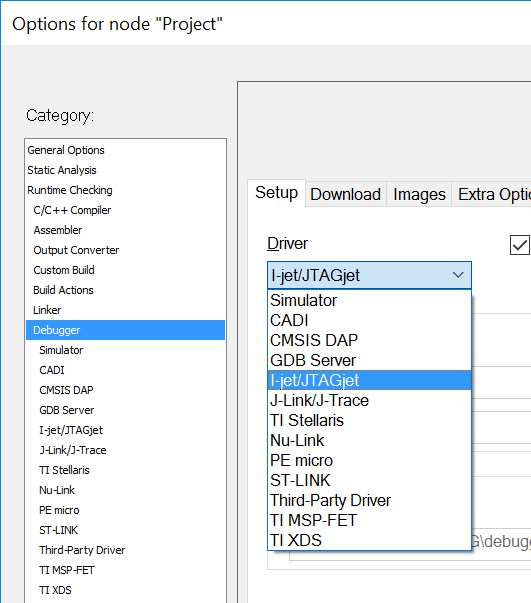
-
Select your debug interface from the "Debugger" category in the options
dialog box. I tested using both the built in STM32Link and an external
I-jet.
-
Still in the "Debugger" category in the options dialog, select the
category specific to your debug interface and ensure the options are
set to "connect under reset" and use the SWD (as opposed to the JTAG)
interface.
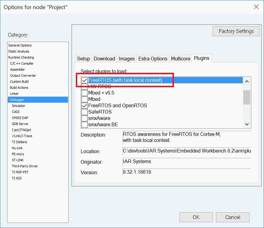
-
Finally in the "Debugger" category, and in preparation for debugging
in Embedded Workbench (see below), select the "Plugins" tab and ensure
the fully thread aware FreeRTOS kernel plug-in is selected. Also select
the WITTENSTEIN StateViewer plug-ins if you have installed them separately.
-
Select "Download->Download Active Project" from the "Project" menu to
program the Cortex-M4 core.
-
Repeat the steps above, but this time for the Cortex-M7 core (so start
by using the drop down at the top of the Workspace window to select the
configuration for the Cortex-M7 core).
-
Press the reset button on the STM32H745 Discover Board and view the
output in the dumb terminal. If all is well you will view a rapid streams
of 1's and 0's scrolling up the terminal window.
To debug the demo application using the built in STLink debug interface:
-
Follow the instructions above to build and run the application, ensuring
STLink is selected as the debug interface, and that the STLink USB connector
CN14 on the STM32H745 Discovery Board is connected to the host computer.
ST provide an application note describing how to configure the STLink
debug settings in the project option to enable dual core debugging. At
the time of writing the project options only enable a single core to be debugged
at a time. Dual core debugging should be possible if you use EWARM V8.40.1
or higher and configure the
debug options as shown in the images below:
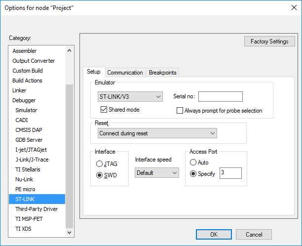 STLink settings required for dual core debugging in the Cortex-M4
project
STLink settings required for dual core debugging in the Cortex-M4
project
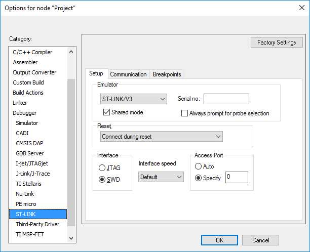 STLink settings required for dual core debugging in the Cortex-M7
project
STLink settings required for dual core debugging in the Cortex-M7
project
-
With the Cortex-M7 project selected as the active project, select
"Download and Debug" from the "Project" menu. A message printed to the
UART by the Cortex-M4 core should show the Cortex-M4 core was also reset.
The debugger should break at the start of the application running on the
Cortex-M7 core, from where you can step through the code, set breakpoints,
inspect variables, etc. as normal.
-
Note that if the application is set running and then the Cortex-M7 core is
stopped in the debugger while the Cortex-M4 core is left running then the
receiving tasks on the
Cortex-M4 core will recognise that messages
have stopped arriving from the Cortex-M7 core and hit an assert().
To prevent that set the value of the
xShortBlockTime variable in prvM4CoreTasks() to portMAX_DELAY so it
does not time out. prvM4CoreTasks() is implemented in the Cortex-M4
main.c file.
-
Select the "Task List" from "FreeRTOS" menu to open the fully thread aware FreeRTOS plug-in windows.
To debug the demo application using an I-jet (both cores together):
-
Follow the instructions above to build and run the application, ensuring
I-jet is selected as the debug interface.
-
With the Cortex-M7 project selected as the active project, open the
project options again.
-
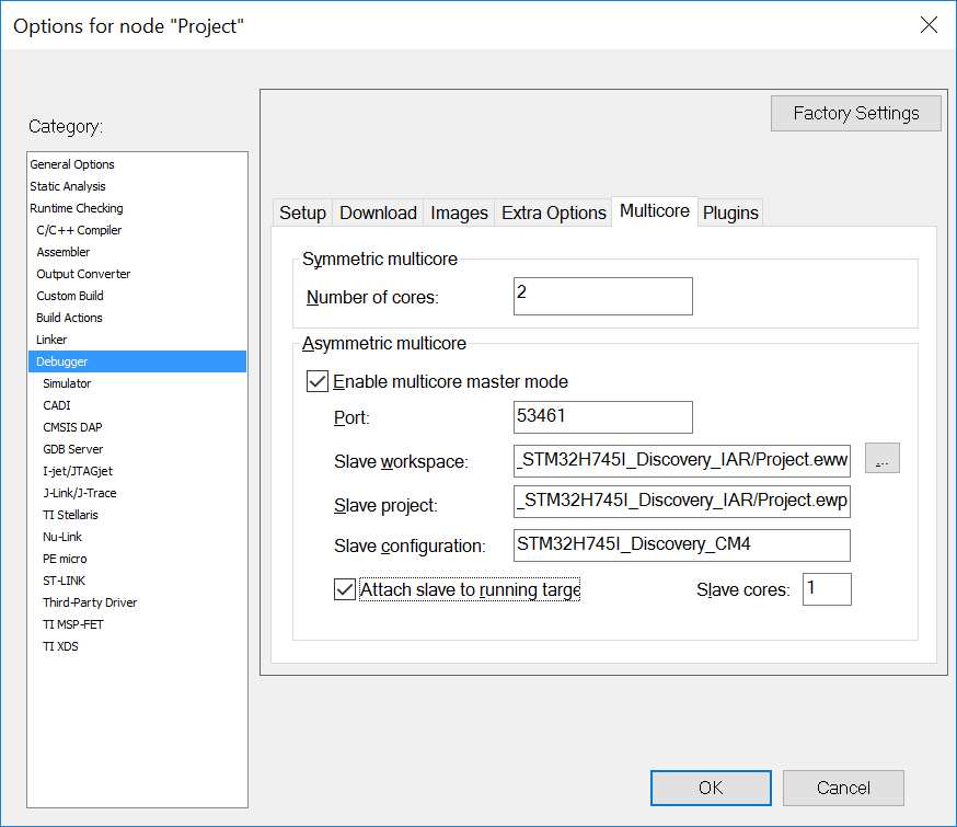
Select the "Multicore" tab in the project options "Debugger" category,
then configure the tab as shown below (click to enlarge) - using
FreeRTOS/Demo/CORTEX_M7_M4_AMP_STM32H745I_Discovery_IAR/Project.eww
as the Slave workspace and FreeRTOS/Demo/CORTEX_M7_M4_AMP_STM32H745I_Discovery_IAR/Project.ewp
as the slave project (the same workspace and project as used for the
Cortex-M7 core - just a different configuration).
-
After closing the project options dialog select
"Download and Debug" from the "Project" menu. The [master] instance
of Embedded workbench will program and then start a debug session
for the Cortex-M7 core. A second [slave] instance of Embedded
Workbench will open automatically and do the same for the Cortex-M4 core.
The master and slave instances of Embedded Workbench are synchronized so
you can now start, stop and debug each core individually or start, stop
and debug both cores at the same time. See
IAR Multicore Debugging
on the IAR website for more details.
-
Note that if the application is set running and then the Cortex-M7 core is
stopped in the debugger while the Cortex-M4 core is left running then the
receiving tasks on the
Cortex-M4 core will recognise that messages
have stopped arriving from the Cortex-M7 core and hit an assert().
To prevent that set the value of the
xShortBlockTime variable in prvM4CoreTasks() to portMAX_DELAY so it
does not time out. prvM4CoreTasks() is implemented in the Cortex-M4
main.c file.
-
Select the "Task List" from "FreeRTOS" menu to open the fully thread aware FreeRTOS plug-in windows.
RTOS port specific configuration
Configuration items specific to the Cortex-M4 build are contained in FreeRTOS/Demo/CORTEX_M7_M4_AMP_STM32H745I_Discovery_IAR/CM4/include/FreeRTOSConfig.h,
configuration items specific to the Cortex-M7 build are contained in FreeRTOS/Demo/CORTEX_M7_M4_AMP_STM32H745I_Discovery_IAR/CM7/include/FreeRTOSConfig.h.
The constants defined in this file can be edited to suit your application. In particular -
-
configTICK_RATE_HZ
This sets the frequency of the RTOS tick interrupt. The supplied value of 1000Hz is useful for
testing the RTOS kernel functionality but is faster than most applications need.
Lowering the frequency will improve efficiency.
-
configKERNEL_INTERRUPT_PRIORITY and configMAX_SYSCALL_INTERRUPT_PRIORITY
See the RTOS kernel configuration documentation for full information on these configuration constants.
-
configLIBRARY_LOWEST_INTERRUPT_PRIORITY and configLIBRARY_MAX_SYSCALL_INTERRUPT_PRIORITY
Whereas configKERNEL_INTERRUPT_PRIORITY and configMAX_SYSCALL_INTERRUPT_PRIORITY
are full eight bit un-shifted values, defined to be used as raw numbers directly
in the ARM Cortex-M NVIC registers, configLIBRARY_LOWEST_INTERRUPT_PRIORITY
and configLIBRARY_MAX_SYSCALL_INTERRUPT_PRIORITY
are equivalents that are defined using just the 4 priority bits implemented in the STM32H7
NVIC.
These values are provided because the CMSIS library function NVIC_SetPriority()
requires the un-shifted 4 bit format.
Attention please!: See the page dedicated to setting interrupt priorities on ARM Cortex-M devices.
It is also recommended to ensure that all priority bits are assigned as
being preemption priority bits, and none as sub priority bits as is done
in the demo project by the function call
HAL_NVIC_SetPriorityGrouping( NVIC_PRIORITYGROUP_4 );
Each port #defines 'BaseType_t' to equal the most efficient data type for that
processor. This port defines BaseType_t to be of type long.
Interrupt service routines
Unlike many FreeRTOS ports, interrupt service routines that cause a context switch have
no special requirements, and can be written as per the compiler documentation.
The macro portYIELD_FROM_ISR() can be used to request a context switch from
within an interrupt service routine.
Note that portYIELD_FROM_ISR() will leave interrupts enabled.
The following source code snippet is provided as an example. The interrupt
uses a direct to task notification
to synchronise with a task (not shown), and calls portYIELD_FROM_ISR
to ensure the interrupt returns directly to the task.
void Dummy_IRQHandler(void)
{
long lHigherPriorityTaskWoken = pdFALSE;

    /* Clear the interrupt if necessary. */
    Dummy_ClearITPendingBit();

    /* This interrupt does nothing more than demonstrate how to synchronise a
    task with an interrupt.  A task notification is used for this purpose.  Note
    lHigherPriorityTaskWoken is initialised to zero. */
    vTaskNotifyGiveFromISR()( xTaskToNotify, &lHigherPriorityTaskWoken );

    /* If the task with handle xTaskToNotify was blocked waiting for the notification
    then sending the notification will have removed the task from the Blocked
    state.  If the task left the Blocked state, and if the priority of the task
    is higher than the current Running state task (the task that this interrupt
    interrupted), then lHigherPriorityTaskWoken will have been set to pdTRUE
    internally within vTaskNotifyGiveFromISR().  Passing pdTRUE into the
    portYIELD_FROM_ISR() macro will result in a context switch being pended to
    ensure this interrupt returns directly to the unblocked, higher priority,
    task.  Passing pdFALSE into portYIELD_FROM_ISR() has no effect. */
    portYIELD_FROM_ISR( lHigherPriorityTaskWoken );
}
Only FreeRTOS API functions that end in "FromISR" can be called from an
interrupt service routine - and then only if the priority of the interrupt
is less than or equal to that set by the configMAX_SYSCALL_INTERRUPT_PRIORITY
configuration constant (or configLIBRARY_MAX_SYSCALL_INTERRUPT_PRIORITY).
Resources used by FreeRTOS
FreeRTOS requires exclusive use of the SysTick and PendSV interrupts. SVC number #0 is also used.
Switching between the pre-emptive and co-operative RTOS kernels
Set the definition configUSE_PREEMPTION within
FreeRTOSConfig.h to 1 to use pre-emption or 0
to use co-operative. The full demo application may not execute correctly when the co-operative RTOS scheduler is
selected.
Compiler options
As with all the ports, it is essential that the correct compiler options are used. The best way to ensure this is to base your
application on the provided demo application files.
Memory allocation
Source/Portable/MemMang/heap_4.c is included in the ARM Cortex-M7 and ARM Cortex-M4 configurations to provide the memory
allocation required by the RTOS kernel.
Please refer to the
Memory Management section of the API documentation for
full information.
Miscellaneous
Note that vPortEndScheduler() has not been implemented.
Copyright (C) Amazon Web Services, Inc. or its affiliates. All rights reserved.