 Debug interface options
Select 'Start rtosdemo.elf' from the RIDE 'Debug' menu.
Debug interface options
Select 'Start rtosdemo.elf' from the RIDE 'Debug' menu.
Functionality
The demo application creates 19 of the
standard demo tasks, a 'check' task, a 'print' task
and the idle task.
The 'print' task is the LCD 'gatekeeper'. That is, it is the only task that should access the LCD directly so is always guaranteed exclusive (and
therefore consistent) access. The print task simply blocks on a queue to wait for messages from other tasks that wish to display text on the LCD.
An arriving message unblocks the task, which writes the message contents to the LCD, before blocking once again. This functionality is included for demonstration
purposes even though in this application there is actually only one task that generates display text.
The 'check' task is responsible for ensuring that all the standard demo tasks are executing as expected. It only executes every three seconds, but
has the highest priority within the system so is guaranteed to get execution time. Any errors discovered by the check task are latched until the
processor is reset. At the end of each cycle the check task sends either a pass or fail message to the 'print' task for display on the LCD.
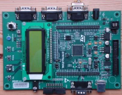
When executing correctly the demo application will behave as follows:
- The LEDs LD2 to LD4 are under control of the 'flash' tasks.
Each will flash at a constant frequency, with LD2 being the fastest and LD4 being the slowest.
-
The LED LD5 is under control of the standard ComTest Tx task. Its state will toggle each time
the ComTest Tx task transmits a character over the RS232 port.
- Most of the standard demo tasks do not update an LED so have no visible indication that they are operating correctly, and are therefore
monitored by the 'check' task.
"Pass" being displayed on the LCD indicates that the check task has never detected an error occurring in any task. The position of the
text is shifted slightly each time it is displayed to provide a visual indication that the check task itself is still executing.
The error detection mechanism can be tested by removing the loopback connector from the serial port while the demo is running, following
which the "Pass" message should change to "Fail".
RTOS port specific configuration
Configuration items specific to this port are contained in
Demo/ARM7_STR75x_GCC/FreeRTOSConfig.h. The constants
defined in this file can be edited to suit your application. In particular - the definition configTICK_RATE_HZ is used to
set the frequency of the RTOS tick. The supplied value of 1000Hz is useful for testing the RTOS kernel functionality but is
faster than most applications require. Lowering this value will improve efficiency.
Each port #defines 'BaseType_t' to equal the most efficient data type for that processor. This port defines
BaseType_t to be of type long.
Note that vPortEndScheduler() has not been implemented.
Interrupt service routines
The STR75x demo saves and restores the task context automatically prior to calling the user defined interrupt service routine C code. This is
contrary to the STR71x port, where the context is saved and restored within the C code via the FreeRTOS provided
macros. This alternative method is provided for demonstration purposes. It has the advantage of simplified syntax from a users perspective, but the
disadvantage of slightly longer execution time for those interrupts in which a context switch is not performed.
An interrupt service routine must be written as an ARM mode C function.
For example:
    void vAnISR( void )
    {
        /* ISR C code goes here. */

        /* Clear the interrupt within the peripheral here. */
    }
Often you will require an interrupt service routine to cause a context switch. For example a serial port character being
received may wake a high priority task that was blocked waiting for the character. If the ISR interrupted a lower priority
task then it should return immediately to the woken task. This can be performed by simply calling the macro portEND_SWITCHING_ISR() from
within the service routine, as demonstrated below:
    void vAnISR( void )
    {
        /* ISR C code goes here. */

        /* Clear the interrupt within the peripheral here. */

        /* Pass in true to cause a context switch, or false to return
        to the interrupted task. */
        portEND_SWITCHING_ISR( pdTRUE );
    }
See the function vSerialISR() within Demo/ARM7_STR75x_GCC/serial/serialISR.c for a complete example.
User defined interrupt routines must replace the ST provided stubs within Demo/ARM7_STR75x_GCC/SystemFiles/ctr0_str75x_FreeRTOS.s.
Switching between the pre-emptive and co-operative RTOS kernels
Set the definition configUSE_PREEMPTION within
Demo/ARM7_STR75x_GCC/FreeRTOSConfig.h to 1 to use pre-emption or 0
to use co-operative.
Compiler options
As with all the ports, it is essential that the correct compiler options are used. The best way to ensure this is to base your
application on the provided demo application project file - as described in the
Source Organization section.
Execution Context
The RTOS scheduler executes in supervisor mode, tasks execute in system mode.
NOTE! :
The processor MUST be in supervisor mode when the RTOS scheduler is started (vTaskStartScheduler is
called). The demo applications included in the FreeRTOS download switch
to supervisor mode prior to main being called. If you are not using one of
these demo application projects then ensure Supervisor mode is entered before calling vTaskStartScheduler().
The stack size of each necessary operating mode is configured using constants defined within Demo/ARM7_STR75x_GCC/SystemFiles/STR75x_COMMON_FreeRTOS.ld. It is not necessary to
configure a stack for User/System mode.
SWI instructions are used by the real time kernel and can therefore not be used by the application code.
Memory allocation
Source/Portable/MemMang/heap_1.c is included in the ARM7 demo application project to provide the memory allocation
required by the real time kernel.
Please refer to the
Memory Management section of the API documentation for
full information.
Serial port driver
It should also be noted that the serial drivers are written to test some of the real time kernel features - and they are not
intended to represent an optimised solution. In particular they do not make use of the FIFO.
Tick Interrupt
The Time Base (TB) peripheral is used to generate the tick interrupt.
Copyright (C) Amazon Web Services, Inc. or its affiliates. All rights reserved.